Like any well-laid-out drivability game plan, a technician prefers one that is designed to expose the symptom but also do so efficiently. With the introduction of the electrified powertrain over 20 years ago, technicians still are reluctant to approach faults related to them, especially drivability symptoms.
The question is “Why?” Well, a lot of it is due to a lack of familiarity and fear of the unknown. But in my experience, even educated technicians struggle to put the puzzle pieces together. With that, many struggle to even realize what the puzzle pieces are (Figure 1).
The players in the game
The first step in understanding how to derive a successful game plan is to identify the components of the system and how they are arranged (or how they work together) to accomplish a goal. The hybrid vehicle not only implements an internal combustion engine (ICE) but also an electrified powertrain.
The hybrid powertrain configuration varies in design between vehicle models but typically falls into two different categories:
- Parallel configuration
- Series-parallel configuration
A parallel configuration is one in which both energy sources of the hybrid powertrain (ICE/electrified system) provide output for propulsion simultaneously. An example of this configuration is one from Honda that has been around since the late 1990s, in their Integrated Motor Assist (IMA) system (Figure 2).
In this configuration, the electrified source provides supplemental torque to the deliberately underpowered ICE. Both the ICE and the single motor-generator (MG) operate together to provide torque input to a transaxle (either a CVT or standard shift manual transaxle).
During regenerative braking, energy (that is normally wasted in the form of heat, from friction) is recaptured as negative MG torque. The rotating magnetic field of the MG (as a “generator”) opposes the rotation of the road wheels and slows the vehicle down as electricity is created and used to charge the high voltage (HV) battery.
The system allows for sufficient vehicle propulsion with improved fuel economy and a reduction in exhaust emissions. If any issues occur with the electrified powertrain, efficiency will plummet. Technicians must be prepared to address and correct these issues when they arise. Without a thorough understanding of how these systems function, this is a difficult task and can be very costly.
An example of a series-parallel hybrid configuration is the Toyota Prius. In this configuration, two (or three, in AWD/4WD configurations) MGs operate alongside an ICE. All these sources can work together, independently, and/or in different combinations to accomplish the goal of propulsion (Figure 3).
Diagnosis of either one of these configurations will be significantly smoother with an understanding of the physics involved, particularly Ohm’s law (How current flow, voltage drop, and temperature relate to one another).
It’s the series-parallel configuration that will be focused upon to prove the point of this article. Regardless of the system’s complexity, a game plan will keep you on the straight and narrow and from finding yourself out in the weeds.
Data-driven diagnostics
Whether facing a vehicle fault that logs a DTC or one that only exhibits a drivability symptom, a logical approach will be your best course of action. But that can’t exist without understanding what data to look at and what that data set is revealing to you.
As I always say, the data should tell a story. This story should reflect aspects of the system being addressed and the conditions in which the vehicle is being operated. Why is this important? Well, the different faults will exhibit under certain operating conditions and may not exhibit under other operating conditions.
If we choose to monitor the correct data (which reflects system/component operation) and at the correct time, we are likely to see the results of that fault reflected in the data. It’s this preliminary data that leads us in the right direction and prevents us from spending time on unnecessary disassembly.
So, let’s choose a scenario to make my case and point. Consider facing a 2018 Lexus RX450h with the complaint of a no-start situation. The root cause is a fuel tank inadvertently filled with diesel (whoops). A full system scan for DTCs reveals nothing pertaining to the HV battery. Monitoring some basic data from the hybrid control module indicated a huge variation in battery cell voltage (Figure 4).
A question that should come to mind in a situation like this is, “What data is available?” This is a function of both the scan tool being used and the data the vehicle manufacturer chooses to provide. This is something that could make the job preliminarily simple on some vehicles and a bit more difficult to acquire on others.
In this case, we used the TechStream, the factory Toyota/Lexus/Scion scan tool for a vehicle of this era. The benefit of using a factory scan tool is it is designed to display all the available data for all the nodes on all the networks that communicate with the scan tool.
Viewing the available data suggests that each of the battery blocks (made up of battery cell pairs) is monitored for voltage (and temperature, as well as resistance if desired). With that, a concern with battery cell voltage should entice another question, “Does a true battery cell voltage issue exist, or is an issue with a malfunctioning voltage sensor circuit present?”
This is a valid concern because I have personally witnessed both potential faults on many a hybrid vehicle. A third question is “How can we differentiate between the two potential faults preliminarily and without much invested time or energy (no disassembly)?” This is where the hybrid analytical road test shines.
Developing the diagnostic game plan
As mentioned previously, a properly conducted analytical road test will include the pertinent data about the system you are addressing and data regarding the driving conditions in which the fault presented itself. Logic will tell you that this analytical road test will vary depending on the type of fault and the system in which the fault resides.
In this case, the fault resides in the HV battery module, and loaded driving conditions would’ve flushed the fault to the surface. With a heavy load on the vehicle, the electrified powertrain will be active, and a significant HV battery current will be flowing at that time. The problem is that this vehicle won't run. The HV battery is depleted from excessive cranking, and we are trying to determine if it is salvageable or requires replacement.
The question we should be trying to answer in most cases like this is regarding a true battery cell block electrical issue or skewed inputs from the sensors that report data to the ECU. This will force us to use our knowledge of electricity and how a battery’s capacitance comes into play. Understanding the physics involved helps in our diagnostic approach.
To evaluate the decline of a battery’s state of health is like viewing the battery as a storage tank. Even though a battery’s state of charge may be sufficient (similar to a full storage tank) a battery’s state of health indicates how much storage capacity is available (poor state of health is like having a shrunken storage tank). What good is having a full tank of fuel if the tank only holds a pint?
So, how does this affect our approach? Well, a true battery cell block performance issue would yield unwanted resistance and associated heat as electrical current flows in and out of the battery. The capacitance (the battery’s ability to store energy) is reduced. As a result, the measured cell voltage should increase rapidly during charging conditions and decrease rapidly during discharging conditions — much like the filling and emptying of a small fuel tank. These expected results are due to the reduction of battery cell capacitance.
How do these anticipated results differ from an issue with a voltage sensor (a perceived performance fault)? I hypothesize that a sensor issue will not be affected by the heat associated with the current flowing in and out of the HV battery, as described above. Unwanted resistance in a sensor circuit will leave the perceived voltage to be displayed as “lower than normal” under every driving condition due to the basic operation of the thermistor circuit.
Said another way, it’s the varying driving conditions of the hybrid analytical road test that preliminarily determines which fault is likely present on the vehicle being addressed. To make this data come alive, we will capitalize on the graphing function of the scan tool to make the faults visible (Figure 5).
The proof is in the pudding
The blue, green and red traces of the graph represent voltage values from three different battery blocks. The yellow trace represents the current load on the HV battery. Looking at the graphed data between battery modules, the evidence is clear on which of the battery blocks is experiencing the issue (red and green). During the discharging/high-load conditions of engine cranking (and/or under electrified system propulsion), the suspect battery blocks’ voltage levels dropped significantly faster than the other healthy battery block. Although there are 14 blocks, only three are being displayed.
Further evidence of a true battery issue would be present by simply viewing the temperature PIDs. Any time current flows across resistance, a voltage drop occurs. With voltage drop comes heat (how a defroster grid works). A temperature PID associated with the suspect battery block will correlate with a voltage drop issue at that module if a true battery block issue is present. If a voltage sensor circuit issue was creating a perceived battery issue and causing the fault, there would not be a rapid increase in temperature (correlating with current flow).
The point? Sufficient evidence would be present reflecting what is OK with the system, and what we should expect to find during further, more involved disassembly. In other words, investing more time will not be a waste of time. Investigating further — with customer approval of the additional, justified diagnostic time — will be time well spent. We are sure to find the root cause of the fault associated with the failure of HV battery block(s).
Think of it like this; imagine knowing ahead of time if replacement of an HV battery (which costs several thousand dollars) was needed? Imagine now if you found that out after disassembly, only to learn the customer did not wish to follow through with the repair. These undesirable circumstances are easily avoidable.
It would be typical to see corrosion as a cause of voltage drop as displayed here (Figure 6). The evidence displayed here correlates with the data obtained. Many times, this corrosion is found at the battery block terminals themselves.
It’s the combination of the data selected and the operating conditions in which the fault occurred that yielded this diagnosis. Although this picture is not from the vehicle we are addressing, it certainly yields similar data. This is because it was derived from loading the HV battery. If the fault was only exhibited on the road, it could surely be established by the hybrid analytical road test. Here is another example from a different vehicle with a battery block issue (Figure 7). We are using a Snap-on Verus to demonstrate how voltage drop prevents block V10 from moving electrical current at the same rate as the other blocks.
To satisfy curiosity, let's take this in a different direction and discuss the data (under similar operating conditions) if the fault was not at the battery itself, but instead was a perceived battery issue due to a faulted voltage sensor circuit.
The graphed data shown here is crucial (Figure 8). Looking first at the numbers to the left, there is no apparent fault present because the refresh rate of the scan data isn’t fast enough to reflect the fault in numerical format, but it’s the graphed data that reveals the fault easily. It not only indicates that battery block voltage in block V01 and V02 are changing rapidly, but it occurs even without load. This is one piece of the puzzle that offers insight into the actual performance of the battery and its state of health being satisfactory.
Furthermore, the battery block voltage is low under all operating conditions. This is the second piece of the puzzle, and it offers insight that points toward a voltage sensor circuit issue. The voltage sensors are located at the battery block terminals (Figure 9).
Looking a bit deeper, we could’ve discovered a third piece of the puzzle relating to the HV battery’s capacitance, through the dynamic portion of this hybrid analytical road test.
In this example, as electrical current would move in and out of the battery, the rate at which the individual cells take on voltage would be unlike the previous example (with damaged battery blocks). In this example of a voltage sensor circuit fault, the rate at which voltage changes would be similar to the other, non-suspect battery blocks. This would offer insight into the state of health and that the battery blocks’ performance would be like the others. Said another way, there would not likely be a true battery module voltage drop issue, but more likely a perceived issue (voltage sensor circuit issue).
Drawing a diagnosis
It should be clear to see that although vehicle technology has changed (and will continue to change) as time goes by, it’s up to us, as professional technicians, to adapt to this changing technology and how we approach drivability faults.
However, one thing that hasn’t changed is the mindset of the approach. We should always strive for three things:
- To understand how the components of the systems work together to accomplish a goal.
- To reference service information for the applicable wiring diagrams and system description and operation.
- To acquire supportive data that displays not only how the system is functioning but also the conditions in which the fault surfaces. In other words, strive to collect and analyze the data that tells a story.
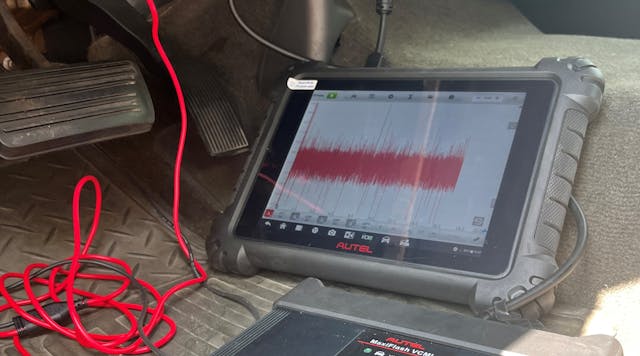
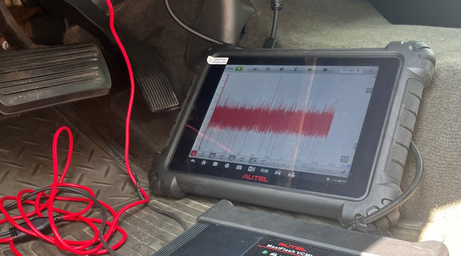
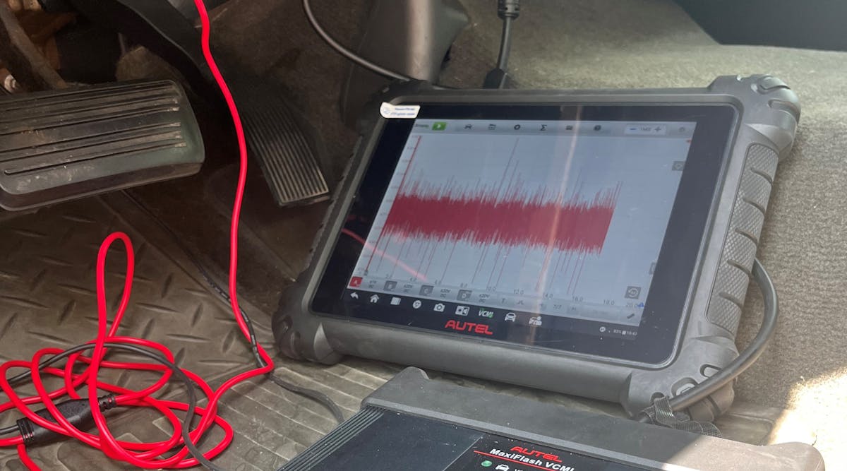
If you take those steps your chances of success are not only great but will also allow for that success in an efficient manner (Figure 10). But don’t take my word for it. Apply these techniques and see for yourself. I'm confident you will find yourself at the front of the pack when it comes to diagnostic skillset, but the confidence that comes with it is the true gift.
